
Hardware reference guide

Hardware Installation
35013379 02 October 2007 771
Mounting
Quantum
Modules
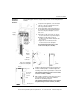
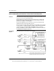
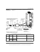
The following figure shows a step-by-step procedure for mounting Quantum
modules.
Power
Supply
Module
Hooks
I/O Bus
Connector
Side view of installing a
module to the backplane
a
b
c
3
1
2
Screw
1
2
3
If required for the application, select and install
a 20 mm or 125 mm mounting bracket to the
rack using standard hardware.
Select and install the appropriate backplane to
the mounting bracket using standard hardware
and remove the plastic backplane connector
dust covers.
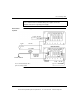
a.
Mount the module at an angle on to the two
hooks located near the top of the backplane.
b.
Swing the module down to make an
electrical connection with the backplane I/O
bus connector.
c.
Tighten the screw at the bottom of the
module to fasten it to the backplane.
The maximum tightening torque for this
screw is 2-4 in-lbs (0.23 - 0.45 Nm).
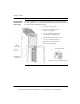
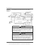
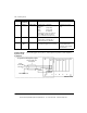
Module
Mounting Screw
Terminal Strip
I/O Screws
Terminal
Strip
Mounting Screw
4
5
Install the appropriate terminal strip (if required) on
t
module, and with a philips screwdriver tighten the
mounting screws at the top and bottom of the termi
n
The maximum tightening torque for the mountin
screws is 10 in-lbs (1.13 Nm).
With a philips screwdriver, make all I/O connections
to the terminal strip as shown in the individual
Quantum module wiring diagrams.
The maximum tightening torque for the terminal
strip field wiring screws is 10 in-lbs (1.13 Nm).
This document provided by Barr-Thorp Electric Co., Inc. 800-473-9123 www.barr-thorp.com