
Hardware reference guide


Hardware Installation
764
35013379 02 October 2007
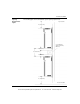
Sixteen Position
Backplane
Figure
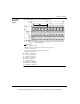
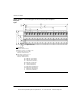
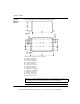
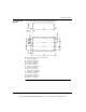
The following figure shows the sixteen position backplane.
A 290 mm / 11.42 inches
B 270 mm / 10.63 inches
C 175.5 mm / 6.91 inches
D 94.5 mm / 3.72 inches
E 10 mm / 0.39 inches
F 15 mm / 0.59 inches
G 670.74 mm / 26.41 inches
H 641.4 mm / 25.25 inches
I 427.6 mm / 16.83 inches
J 213.8 mm / 8.42 inches
Ground Screws
A
B
C
D
E
F
I
G
H
J
=Mounting Hole
Diameter: 8mm/0.31 inches.
=Optional locations for Modbus Plus
communication cable grounding.
Diameter: 8 mm/0.31 inches
=Threaded mounting holes for
half and full height modules.
Diameter: 4mm/0.16 inches
This document provided by Barr-Thorp Electric Co., Inc. 800-473-9123 www.barr-thorp.com