
Hardware reference guide


Hardware Installation
758
35013379 02 October 2007
Hardware Installation – Selecting Backplanes
Overview Backplanes are designed to mechanically secure and electrically connect all
modules used in drops. The backplane contains a passive circuit board which
permits modules to communicate with each other and to identify their slot numbers
without further switch settings.
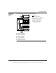
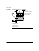
Refer to the following tables for front view illustrations and dimensions of the
backplanes (all backplane dimensions are nominal).
The recommended length for the mounting screws should be within the following
range: 0.24 in. (6 mm) - 0.52 in. (13 mm)
The head height of the screws should not exceed 0.14 in. (3.5 mm). 1/4' X 20 screws
are recommended.
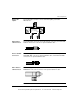
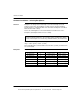
Backplanes The following table shows the backplanes.
Note: To meet vibration/shock specifications, the backplane must be mounted
using all specified mounting holes. The mounting surface should be flat to within +/
- 1.0 mm. The backplane is mounted using standard hardware (described below).
Part Number Module Slots Weight (Old Model) Weight (New Model)
140 XBP 002 00 2 0.5 lbs (0.23 kg) 0.9 lbs (0.41 kg)
140 XBP 003 00 3 0.75 lbs (0.34 kg) 1.35 lbs (0.62 kg)
140 XBP 004 00 4 1.0 lbs. (0.45 kg) 1.8 lbs (0.82 kg)
140 XBP 006 00 6 1.4 lbs (0.64 kg) 2.7 lbs (1.23 kg)
140 XBP 010 00 10 2.2 lbs (1.0 kg) 4.5 lbs (2.04 kg)
140 XBP 016 00 16 3.5 lbs (1.58 kg) 7.2 lbs (3.27 kg)
This document provided by Barr-Thorp Electric Co., Inc. 800-473-9123 www.barr-thorp.com