
Hardware reference guide

Power Supplies
74
35013379 02 October 2007
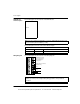
LED Indicator
and Description
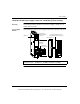
The following figure shows the CPS11100 LED indicator.
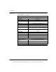
The following table shows the CPS11100 LED description.
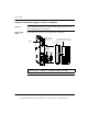
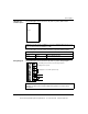
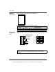
Wiring Diagram The following figure shows the CPS11100 wiring diagram.
Note: For "Closed System" installations, connector 140XTS00 500 must be used
(refer to Closed System Installation, p. 795 ).
LED Description
LEDs Color Indication when On
Pwr ok Green Power is supplied to the bus.
Pwr ok
Note: See Power and Grounding Considerations for AC and DC Powered
Systems, p. 776 for power and grounding wiring guidelines and operational
information.
Do not connect any
external wiring to
Install jumper for 115 Vac
operation only
AC L
AC N
1
2
3
4
5
6
7
}
Internally connected
these points
This document provided by Barr-Thorp Electric Co., Inc. 800-473-9123 www.barr-thorp.com