
Hardware reference guide

I/O Modules
692
35013379 02 October 2007
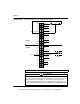
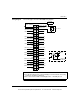
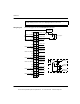
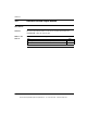
Wiring Diagram The following figure shows the DDO885 wiring diagram.
Note: N / C = Not Connected.
–
+
OUTPUT 9
OUTPUT 10
FIELD
DEVICE
+–
GROUP A RETURN
OUTPUT 1
N/C
OUTPUT2
OUTPUT 3
OUTPUT 4
N/C
OUTPUT 5
OUTPUT 6
OUTPUT 7
N/C
N/C
OUTPUT 8
GROUP B RETURN
N/C
OUTPUT 11
OUTPUT 12
N/CN/C
GROUP B SUPPLY
GROUP A SUPPLY
N/C
N/C
N/C
N/C
N/C
N/C
N/C
N/C
N/C
N/C
N/C
N/C
N/C
N/C
N/C
N/C
N/C
GROUP A
GROUP B
2
10
4
6
8
12
14
16
18
20
22
24
26
28
30
32
34
36
38
40 39
37
35
33
31
29
27
25
23
21
19
17
15
13
11
9
7
5
3
1
Reverse Polarity Possibility
This module is not protected against reverse polarity. If you want to protect against
polarity miswiring, an external diode in series with each group supply line is
recommended. This diode must be able to support the group load current.
Failure to follow these instructions can result in injury or equipment damage.
CAUTION
This document provided by Barr-Thorp Electric Co., Inc. 800-473-9123 www.barr-thorp.com