
Hardware reference guide


I/O Modules
35013379 02 October 2007 677
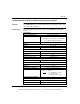
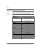
Load Inductance Maximum 0.5 Henry @ 4 Hz switch frequency
or
where:
L = Load Inductance (Henry)
I = Load Current (A)
F = Switching Frequency (Hz)
Load Capacitance Maximum 50 μf
Tungsten Load Maximum 12 W @ 24 Vdc
Output Protection (internal) Transient voltage suppression: 36 V
Bus Current Required 330 mA max
Power Dissipation 2.0 W + (0.4 V x Total Load Current)
External Power 19.2 ... 30 Vdc
Fusing
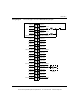
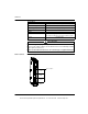
Internal 5.0 A fuse per group. Part # 043502405. For the
location of the fuses see Fuse Locations, p. 678.
External Each group is protected with a 5 A fuse to protect the
module from catastrophic failure. The group fuse is not
guaranteed to protect each output switch for all
possible overload conditions. It is recommended that
each point be protected with a 3/4 A, 250 V fuse,
Part # 57-0078-000.
Specifications
L =
0.5
I
2
F
Access to Fuses
Turn off power to the module and remove the field wiring terminal strip to gain
access to fuses.
Failure to follow these instructions can result in injury or equipment damage.
CAUTION
This document provided by Barr-Thorp Electric Co., Inc. 800-473-9123 www.barr-thorp.com