
Hardware reference guide


I/O Modules
35013379 02 October 2007 655
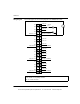
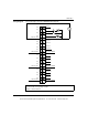
The following figure shows the DAO84220 derating chart.
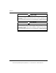
Surge Current Maximum (rms) Per Point Per Group
One Cycle 30 A 45 A
Two Cycles 20 A 30 A
Three Cycles 10 A 25 A
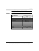
Applied DV/DT 400 V/μs
Output Protection RC snubber suppression (internal)
Isolation (rms)
Group to Group 1000 Vac for 1 minute. Galvanically Isolated.
Output to Bus 1780 for 1 minute
Fault Detection Blown fuse detect, loss of field power
Bus Current Required 350 mA
Power Dissipation 1.85 W + 1.1 V x Total Module Load Current
External Power Supply (rms) 20 ... 56 Vac
Fusing
Internal 5 A fuse for each group
(Part # 043502405 or equivalent)
For the location of the fuses see Fuse Locations, p. 656.
External User discretion
Specifications
17
16
15
14
13
12
11
10
9
8
7
6
5
4
3
2
1
30 35 40 45 50 55 60
20-56 V rms
AMBIENT TEMPERATURE (deg. C)
TOTAL MODULE CURRENT (A)
0
This document provided by Barr-Thorp Electric Co., Inc. 800-473-9123 www.barr-thorp.com