
Hardware reference guide

I/O Modules
650
35013379 02 October 2007
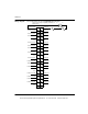
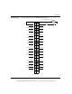
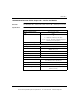
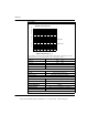
The following figure shows the DAO84210 derating chart.
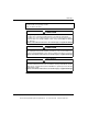
Surge Current Maximum (rms) Per Point Per Group
One Cycle 30 A 45A
Two Cycles 20 A 30 A
Three Cycles 10 A 25 A
Applied DV / DT 400 V/μs
Response
OFF - ON 0.50 of one line cycle max
ON - OFF 0.50 of one line cycle max
Output Protection RC snubber suppression (internal)
Isolation (rms)
Group to Group 1000 Vac rms for 1 minute, galvanically isolated
Output to Bus 1780 Vac rms for 1 minute
Fault Detection Blown fuse detect, loss of field power
Bus Current Required 350 mA
Power Dissipation 1.85 W + 1.1 V x Total Module Load Current
External Power (rms) 85 ... 253 Vac
Fusing
Specifications
17
16
15
14
13
12
11
10
9
8
7
6
5
4
3
2
1
30 35 40 45 50 55 60
20-132 V rms
170-253 V rms
AMBIENT TEMPERATURE (deg. C)
TOTAL MODULE CURRENT (A)
DAO84210 Operating Curve*
*The specifications stated are pending UL/CSA approval. This module was originally approved at 2 A
each point; and 12 A, 0 ... 50° C (115 Vac) and 0 ... 50° C (230 Vac) per module.
This document provided by Barr-Thorp Electric Co., Inc. 800-473-9123 www.barr-thorp.com