
Hardware reference guide


I/O Modules
35013379 02 October 2007 637
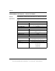
I/O Map Register
Assignment
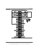
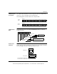
The output modules listed above can be configured as either 32 contiguous 0x
references, or as two 4x registers in the following format.
The following figures show the formats for the output modules.
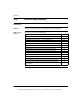
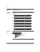
I/O Map Status
Byte
The I/O map status byte (not including 140DAO85300 module) is used by the
modules as follows:
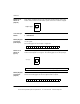
Module Zoom
Selections
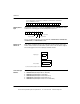
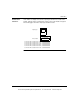
Push <Enter> to display and select the output type and the timeout state for the
module. Timeout state is assumed when system control of the module is stopped.
The following figure shows the output type and timeout state.
1234567 10 11 12 13 14 15 1689
17 18 19 20 21 22 23 26 27 28 29 30 31 3224 25
Output
Point 1
Register 2
MSB - First Word
Register 1
MSB - Second Word
Output
Point 17
Groupt A Fault
12345678
Group B Fault
Group C Fault
Group D Fault
Group A Point Fault
Group B Point Fault
Group C Point Fault
Group D Point Fault
140DDO35301 Module only
(overload or short circuit)
Missing field power
or blown fues
BIN
BCD
Last Value
User Defined
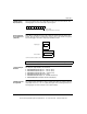
Timeout State:
Output Type:
User Defined Timeout State Points 1-16: 0000000000000000
User Defined Timeout State Points 17-32: 0000000000000000
This document provided by Barr-Thorp Electric Co., Inc. 800-473-9123 www.barr-thorp.com