
Hardware reference guide

I/O Modules
35013379 02 October 2007 573
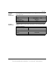
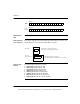
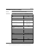
Output Section 2 Channels
Input Section 4 Channels
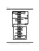
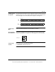
Typical Wiring Outputs
Channel 1 The output shows a connection to an external field device
and optional monitor.
Channel 2 The output shows a connection to an external field device
and the input of channel 1.
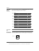
Typical Wiring Inputs
Channel 1 Channel 1 shows 4 - 20 mA current input controlled by
output section Channel 2.
Channel 4 The input shows a connection to a voltage output sensor.
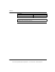
Note:
1. Pins 1 ... 20 are outputs
Pins 21 ... 40 are inputs
2. N / C = Not Connected
3. Jumpers are required between IN (+) and SENSE terminals for all current input
ranges.
This document provided by Barr-Thorp Electric Co., Inc. 800-473-9123 www.barr-thorp.com