
Hardware reference guide

I/O Modules
572
35013379 02 October 2007
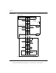
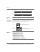
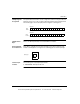
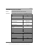
Wiring Diagram The following figure shows the wiring diagram for the 140 AMM 090 00 analog input/
output module.
The following information pertains to the wiring diagram above.
2
4
6
8
12
14
16
18
20 19
17
15
13
11
9
7
5
3
1
22
24
26
28
30
32
34
36
38
40 39
37
35
33
31
29
27
25
23
21
CURRENT SOURCE(-)1
CURRENT SOURCE(-)1
N/C
N/C
CURRENT SOURCE(-)1
CURRENT SOURCE(-)2
CURRENT SOURCE(-)2
N/C
N/C
CURRENT SOURCE(-)2
IN(-)1
N/C
IN(-)2
N/C
N/C
IN(-)3
N/C
IN(-)4
N/C
N/C N/C
SENSE 4
IN(+)4
SENSE 3
IN(+)3
N/C
SENSE 2
IN(+)2
SENSE 1
CURRENT SINK(+)2
N/C
N/C
N/C
MONITOR 2
CURRENT SINK(+)1
N/C
N/C
N/C
MONITOR 1
+–
Optional Monitor
Voltmeter
1 V= 4 mA
5 V= 20 mA
24 Vdc
Field
Supply
Field
Device
Field
Device
4 - 20 mA
Current
4 - 20 mA
Current
IN(+)1
–
+
Sensor
0 - 10 V
Output
+
_
10
V
This document provided by Barr-Thorp Electric Co., Inc. 800-473-9123 www.barr-thorp.com