
Hardware reference guide

I/O Modules
35013379 02 October 2007 569
Input
Specifications
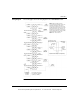
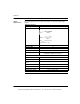
The following table shows the input specifications for the analog input/output
module.
Input Specifications
Operating Ranges
Bipolar +/- 10 Vdc +/-5 Vdc +/- 20 mA
Unipolar 0 ... 10 Vdc 0 ... 5 Vdc 0 ... 20 mA
Unipolar w/Offset 1 ... 5 Vdc 4 ... 20 mA
Voltage Input
Linear Measuring Range 2.4% over and under range
Absolute Maximum Input +/- 50 Vdc
Input Impedance In Range >10 MΩ
Input Impedance Over Range > 0.5 MΩ
Current Input
Linear Measuring Range +2.4% over range, and -9.6% under range
Absolute Maximum Input +/- 25 mA
Input Impedance 250Ω
Resolution
16 Bit +/- 10 Vdc 0 ...10 Vdc
15 Bit +/- 5 Vdc 0 ... 5 Vdc +/-20 mA 0 ... 20 mA
14 Bit 1 ... 5 Vdc 4 ... 20 mA
Absolute Accuracy Error @
25° C (Voltage Mode)
Typical:
Maximum:
+/- 0.03%
+/- 0.05% of full scale
Linearity Monotonic +/- 1 LSB
Offset 0 ... 60° C
Gain Shift 0 ... 60° C
+/- 0.0014%/°C of full scale max
+/- 0.002%/°C of full scale max
Common Mode Rejection Better than 80 dB @ 50 or 60 Hz
Input Filter Single pole low pass, -3dB @ 21 Hz, +/- 20%
Operating Voltage
Channel to Channel +/- 40 Vdc max
Isolation
Channel to Bus 500 Vac, 750 Vdc, for 1 minute
Input Channel to Output
Channel
500 Vac, 750 Vdc, for 1 minute
Update Time 320 ms for 4 channels
Fault Detection Open circuit in 4 ... 20 mA range, or over range, or under
range in bipolar modes only
This document provided by Barr-Thorp Electric Co., Inc. 800-473-9123 www.barr-thorp.com