
Hardware reference guide

I/O Modules
35013379 02 October 2007 565
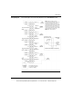
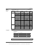
Linear
Measuring
Ranges
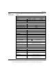
The following table shows the linear measuring ranges for the 140AMM09000
combination Analog module.
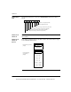
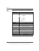
4x Registers The following figure shows the 4X registers.
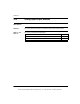
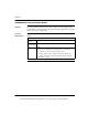
Data Format Input Under
Warning
Normal Over
Warning
16-bit
Format
+/- 10 V < 768 768 ... 64,768 > 64,768
+/- 5 V, +/- 20 mA < 16,768 16,768 ... 48,768 > 48,768
0 ... 10 V 0 ... 64,000 > 64,000
0 ... 5 V, 0 ... 20 mA 0 ... 32,000 > 32,000
1 ... 5 V, 4 ... 20 mA < 6,400 6,400 ... 32,000 > 32,000
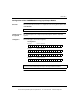
Voltmeter
Format*
+/- 10 V < -10,000 -10,000 ... 10,000 > 10,000
+/- 5 V < -5,000 -5,000 ... 5,000 > 5,000
0 ... 10 V 0 ... 10,000 > 10,000
0 ... 5 V 0 ... 5,000 > 5,000
1 ... 5 V < 1,000 1,000 ... 5,000 > 5,000
+/- 20mA < -20,000 -20,000 ... 20,000 > 20,000
0 ... 20mA 0 ... 20,000 > 20,000
4 ... 20mA < 4,000 4000 ... 20,000 >20,000
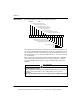
12-bit
Format
+/- 10 V 0 0 ... 4,095 4,095
+/- 5 V, +/- 20 mA 0 0 ... 4,095 4,095
0 ... 10 V 0 ... 4,095 4,095
0 ... 5 V, 0 ... 20 mA 0 ... 4,095 4,095
1 ... 5 V, 4 ... 20 mA 0 0 ... 4,095 4,095
Note: The data format is always 0 ... 4095 decimal (in Modsoft).
Channel 1 output dataRegister 1
Channel 2 output dataRegister 2
4x Registers
This document provided by Barr-Thorp Electric Co., Inc. 800-473-9123 www.barr-thorp.com