
Hardware reference guide

I/O Modules
35013379 02 October 2007 561
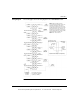
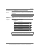
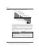
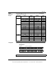
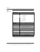
Wiring Diagram The following figure shows the wiring diagram for the 140AVO02000 module.
COMMON 1 (-)
COMMON 1 (-)
MASTER OVERRIDE
N/C
COMMON 1 (-)
COMMON 2 (-)
COMMON 2 (-)
MASTER OVERRIDE
N/C
COMMON 2 (-)
COMMON 3 (-)
COMMON 3 (-)
MASTER OVERRIDE
N/C
COMMON 3 (-)
COMMON 4 (-)
COMMON 4 (-)
MASTER OVERRIDE
N/C
COMMON 4 (-)
See
NOTE 1
See
NOTE 1
See
NOTE 1
See
NOTE 1
OUTPUT 1 (+)
R 1
N/C
OUTPUT 2 (+)
CONTROL 1
REFERENCE 1
Jumper
Jumper
R 2
Jumper
CONTROL 2
REFERENCE 2
N/C
OUTPUT 3 (+)
Jumper
R 3
CONTROL 3
Jumper
REFERENCE 3
N/C
OUTPUT 4 (+)
Jumper
R 4
CONTROL 4
REFERENCE 4
N/C
1/16A
EXTERNAL
VOLTAGE
SOURCE
The external voltage source
is not required for standard
operation (see NOTE 1).
FIELD
DEVICE
FIELD
DEVICE
CHANNEL 4
JUMPERED
FOR 0 TO 10 V
CHANNEL 3
JUMPERED
FOR +/-5 V
CHANNEL 2
JUMPERED
FOR 0 TO 5 V
CHANNEL 1
JUMPERED
FOR +/-10 V
NOTE 1: Master override is an input
connected via an internal relay contact to the
output when the module is not active. If
connected to an external source, the master
override input must be fused by a 1/16 A fuse.
If the master override is not connected to an
external source, then it must be connected to
common of that channel. The master override
relay transition time is typically 2 ms.
NOTE 2: N/C = Not Connected
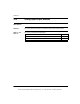
Normally Open when
CH X green LED is ON
Normally
Open
Normally
Closed
Channel
Output X
Master
Override X
Typical one
of four
Master Override Relay Circuit (Internal)
21
43
56
87
10 9
12 11
1314
16 15
1718
20 19
2122
24 23
2526
28 27
2930
32 31
3334
36 35
3738
40 39
This document provided by Barr-Thorp Electric Co., Inc. 800-473-9123 www.barr-thorp.com