
Hardware reference guide

I/O Modules
35013379 02 October 2007 557
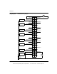
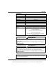
Notes on Wiring
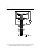
Diagram
1. At power up, channel outputs are all at zero current (0 mA).
2. VM is an optional voltmeter that can be connected to read voltage that is
proportional to the current. Wiring to this terminal is limited to 1 meter maximum.
3. Either shielded or unshielded cables may be used. In noisy environments, twisted
shielded cable is recommended. Shielded cable should have a shield tied to earth
ground near the signal source end.
4. Unused outputs may cause the activation of the F (fault) LED. To avoid this
occurrence the unused channels should be configured in the 0 ... 25 mA range.
5. All terminals labeled ‘RETURN" are common inside the module.
6. N/C = Not connected
This document provided by Barr-Thorp Electric Co., Inc. 800-473-9123 www.barr-thorp.com