
Hardware reference guide

I/O Modules
35013379 02 October 2007 553
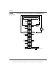
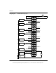
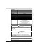
Note:
1. Unused channels will indicate broken wire status unless wired to the loop
supply, as shown on Channel 4. In this example, loop supply must be 30 V or
less.
2. VM is an optional voltmeter that can be connected to read voltage that is
proportional to the current. Wiring to this terminal is limited to 1 meter maximum.
3. The wiring example shows Channel 1 acting as a current sink and Channel 2
acting as a current source for their respective field devices.
4. N / C = Not Connected.
Note: At power up, the channel outputs are all disabled (current = 0). Configuring
any channel as disabled will cause all channels to be disabled when a
communication loss occurs.
This document provided by Barr-Thorp Electric Co., Inc. 800-473-9123 www.barr-thorp.com