
Hardware reference guide

I/O Modules
546
35013379 02 October 2007
I/O Configuration for Analog Output Modules
Overview This section provides information on the configuration of analog output modules.
These modules are:
z 140ACO02000
z 140ACO13000
z 140AIO33000
z 140AVO02000
140ACO02000 The following information pertains to configuration of the 140ACO02000 Analog
Output module.
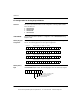
I/O Map Register
Assignment
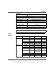
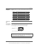
This module requires four contiguous output (4x) registers, which are assigned as
follows. The following figure shows the register assignments.
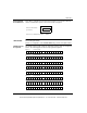
I/O Map Status
Byte
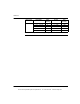
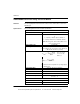
The four least significant bits in the I/O map status byte are used for the
140ACO02000 Output module. The following figure shows the status byte register.
Channel 1 data (0 ... 4,095 = 4 ... 20 mA)Register 1
Register 2
Register 3
Register 4
Channel 2 data (0 ... 4,095 = 4 ... 20 mA)
Channel 3 data (0 ... 4,095 = 4 ... 20 mA)
Channel 4 data (0 ... 4,095 = 4 ... 20 mA)
Channel 1 loop broken wire
Channel 2 loop broken wire
12345678
Channel 3 loop broken wire
Channel 4 loop broken wire
This document provided by Barr-Thorp Electric Co., Inc. 800-473-9123 www.barr-thorp.com