
Hardware reference guide

I/O Modules
35013379 02 October 2007 529
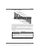
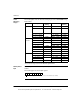
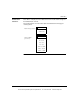
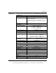
Specifications The following table shows the specifications for the ACI04000 analog input module.
Specifications
Number of Channels 16 Differential or 16 externally tied single ended
LEDs Active: Indicates Bus communication is present
F: Indicates channel fault.
NOTE: This module produces a fault signal F if any one
channel detects a broken wire condition in the 4 ... 20 mA
range.
Required Addressing 17 Words In
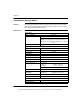
Current Input
Linear Measuring Range 0 ... 25 mA, 0 ... 25,000 counts
0 ... 20 mA, 0 ... 20,000 counts
4 ... 20 mA, 0 ...16,000 counts
4 ... 20 mA, 0 ... 4,095 counts
Absolute Maximum Input 30 mA
Input Impedance 250 Ω nominal
Accuracy Error @ 25° C +/- 0.125% of full scale
Linearity (0 to 60°C) +/- 6μA max, 0 ... 25 mA, 0 ... 25,000 counts
+/- 6μA max, 0 ... 20 mA, 0 ... 20,000 counts
+/- 6μA max, 4 ... 20 mA, 0 ... 16,000 counts
+/- 12μA max, 4 ... 20 mA, 0 ... 4,095 counts
Accuracy Drift w/
Temperature
Typical:
Maximum:
+/- 0.0025% of full scale / °C
+/- 0.005% of full scale / °C
Common Mode Rejection > -90 dB @ 60Hz
Input Filter Single pole low pass, -3 dB cutoff @ 34 Hz, +/- 25%
Isolation
Field to bus 1780 Vac for 1 minute
Operating Voltage
Channel to Channel 30 Vdc max
Update Time 15ms for all 16 channels
Fault Detection Broken wire in 4 ... 20 mA mode
Bus Current Required 360 mA
Power Dissipation 5 W
External Power Not required for this module
Fusing
Internal None
External User discretion
This document provided by Barr-Thorp Electric Co., Inc. 800-473-9123 www.barr-thorp.com