
Hardware reference guide

I/O Modules
526
35013379 02 October 2007
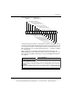
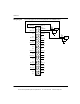
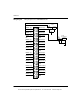
Wiring Diagram The following figure shows the wiring diagram for the ACI030 module.
2
10
4
6
8
12
14
16
18
20
22
24
26
28
30
32
34
36
38
40 39
37
35
33
31
29
27
25
23
21
19
17
15
13
11
9
7
5
3
1
N/C
INPUT 2(-)
INPUT 1(-)
N/C
N/C
INPUT 3(-)
N/C
INPUT 4(-)
N/C
N/C
INPUT 5(-)
N/C
INPUT 6(-)
N/C
N/C
INPUT 7(-)
N/C
INPUT 8(-)
N/C
N/C N/C
I SENSE 8
INPUT 8(+)
I SENSE 7
INPUT 7(+)
N/C
I SENSE 6
INPUT 6(+)
I SENSE 5
INPUT 5(+)
N/C
I SENSE 4
INPUT 4(+)
I SENSE 3
INPUT 3(+)
N/C
I SENSE 2
INPUT 2(+)
INPUT 1(+)
I SENSE 1
Jumper
Voltage
Source
Current
Source
-
+
-
+
This document provided by Barr-Thorp Electric Co., Inc. 800-473-9123 www.barr-thorp.com