
Hardware reference guide

I/O Modules
522
35013379 02 October 2007
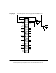
Linear
Measuring
Ranges
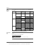
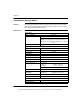
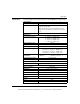
The following table shows the linear measuring ranges for the 140AVI03000 Analog
Input module.
*The Voltmeter ranges are listed in Modsoft signed format.
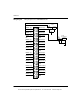
I/O Map Status
Byte
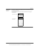
The most significant bit in the I/O map status byte is used for the 140AVI03000 Input
module.
The following figure shows the input register.
Data Format Input Under
Warning
Normal Over
Warning
16-bit Format +/- 10 V < 768 768 ... 64,768 > 64,768
+/- 5 V, +/- 20 mA <16,768 16,768 ... 48,768 > 48,768
0 ... 10 V 0 ... 64,000 > 64,000
0 ... 5 V, 0 ... 20 mA 0 ... 32,000 > 32,000
1 ... 5 V, 4 ... 20 mA <6,400 6,400 ... 32,000 > 32,000
Voltmeter
Format*
+/- 10 V < –10,000 –10,000 ...10,000 > 10,000
+/- 5 V < –5,000 –5,000 ... 5,000 > 5,000
0 ... 10 V 0 ... 10,000 > 10,000
0 ... 5 V 0 ... 5,000 > 5,000
1 ... 5 V < 1,000 1,000 ... 5,000 > 5,000
+/- 20 mA < –20,000 –20,000... 20,000 > 20,000
0 ... 20 mA 0 ... 20,000 > 20,000
4 ... 20 mA < 4,000 4,000 ... 20,000 > 20,000
12-bit Format +/- 10 V 0 0 ... 4,095 4,095
+/- 5 V, +/- 20 mA 0 0 ... 4,095 4,095
0 ... 10 V 0 ... 4,095 4,095
0 ... 5 V, 0 ... 20 mA 0 ... 4,095 4,095
1 ... 5 V, 4 ... 20 mA 0 0 ... 4,095 4,095
1 = Out of range or broken field wire on one or more channels (4 .. 20 mA)
12345678
This document provided by Barr-Thorp Electric Co., Inc. 800-473-9123 www.barr-thorp.com