
Hardware reference guide

I/O Modules
35013379 02 October 2007 511
I/O Map Register
Assignments-
Register 17
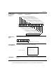
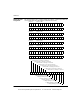
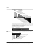
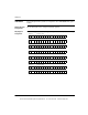
The following figure shows the status warnings for register 17.
I/O Map Status
Byte
I/O map status byte is used as follows:
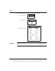
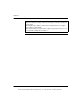
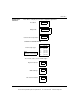
Modsoft Module
Zoom Selections
Push <Enter> to display and select the channel range.
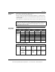
140ARI03010 The following information pertains to configuration of the 140ARI03010 Analog Input
module.
Input Status WordRegister 17
1 = Broken wire (4 ... 20 mA only) on channel 13
1 = Broken wire (4 ... 20 mA only) on channel 14
1 = Broken wire (4 ... 20 mA only) on channel 15
1 = Broken wire (4 ... 20 mA only) on channel 16
1234567 10 11 12 13 14 15 1689
1 = Broken wire (4 ... 20 mA only) on channel 8
1 = Broken wire (4 ... 20 mA only) on channel 7
1 = Broken wire (4 ... 20 mA only) on channel 6
1 = Broken wire (4 ... 20 mA only) on channel 5
1 = Broken wire (4 ... 20 mA only) on channel 9
1 = Broken wire (4 ... 20 mA only) on channel 10
1 = Broken wire (4 ... 20 mA only) on channel 11
1 = Broken wire (4 ... 20 mA only) on channel 12
1 = Broken wire (4 ... 20 mA only) on channel 4
1 = Broken wire (4 ... 20 mA only) on channel 3
1 = Broken wire (4 ... 20 mA only) on channel 2
1 = Broken wire (4 ... 20 mA only) on channel 1
Note: The broken wire detect is set at 2.0 mA.
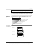
1 = Broken wire (4 ... 20 mA only)
12345678
4 to 20mA 0 to 16,000
4 to 20mA 0 to 4095
4 to 20mA 0 to 20,000
0 to 25mA 0 to 25,000
Channel X range selection:
This document provided by Barr-Thorp Electric Co., Inc. 800-473-9123 www.barr-thorp.com