
Hardware reference guide

I/O Modules
35013379 02 October 2007 499
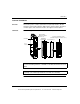
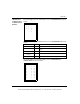
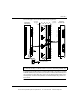
The following figure shows the I/O module keying assignments.
To support keying, all I/O modules accepting terminal strips come with 12 customer-
installable primary keys (six yellow keys each for the module and terminal strip) and
six secondary keys (three white keys each for the module and terminal strip). In the
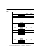
following table, check the Primary Module and Terminal Strip Coding columns for
key locations.
Note: The primary/secondary keys shown (in black) in this example reflect the
recommended coding of a 24 Vdc module in slot 6 to its field wiring terminal strip.
X
Right Side of
Terminal Strip
Secondary
Key Slots
Primary
Key Slots
Left Side of
Terminal Strip
A
B
C
D
E
F
F
E
D
C
B
A
A
B
C
D
E
F
F
E
D
C
B
A
1
2
3
4
5
6
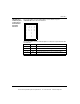
Install the key into the
slot round end first.
1
2
3
4
5
6
This document provided by Barr-Thorp Electric Co., Inc. 800-473-9123 www.barr-thorp.com