
Hardware reference guide

I/O Modules
496
35013379 02 October 2007
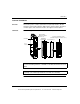
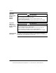
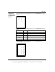
The following table shows the LED descriptions for the 140DAM59000 and
140DDM39000 bi-directional modules.
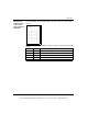
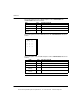
The following table shows the LED indicators for the 140DDM69000 bi-directional
module.
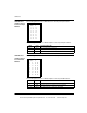
The following table shows the LED descriptions for the 140DDM69000 bi-directional
modules.
LEDs Color Indication when ON
Active Green Bus communication is present.
F Red A fault (external to the module) has been detected.
1 and 8 (left columns) Green The indicated output point and channel is turned ON.
1 and 16 (right two
columns)
Green The indicated input point and channel is turned ON.
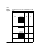
LEDs Color Indication when ON
Active Green Bus communication is present.
F Red Over current condition on any point.
1 and 4 (left columns) Green The indicated output point is turned ON.
1 and 4 (middle
columns)
Red The indicated output point has an over current condition.
1 and 4 (right
columns)
Green The indicated input point is turned ON.
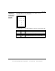
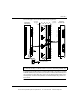
Active F
111
222
333
444
This document provided by Barr-Thorp Electric Co., Inc. 800-473-9123 www.barr-thorp.com