
Hardware reference guide

I/O Modules
35013379 02 October 2007 491
Quantum I/O Modules
Overview The following section contains specifications for input/output modules. Module
descriptions include wiring diagrams, LED indicators and descriptions, illustrations
of module figures, and, for discrete modules, true high/true low descriptions.
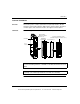
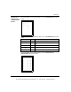
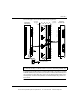
I/O Module The following figure shows the I/O modules and its components.
Note: When field wiring the I/O modules, the maximum wire size that should be
used on a field wiring terminal is 1-14 AWG or 2-16 AWG; the minimum size is 20
AWG.
Note: The field wiring terminal strip (Modicon #140XTS00200) must be ordered
separately. (The terminal strip includes the removable door and label.)
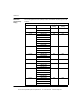
140
DDO 843 00
10 80 vdc out
X
X
X
X
X
X
X
X
X
X
X
X
X
X
X
X
X
X
X
X
X
X
X
X
X
X
X
X
X
X
X
X
X
X
X
X
X
X
X
X
X
X
X
Removable Door
Customer Identification Label
(Fold label and place it inside the door)
Field Wiring
Terminal Strip
Model Number
Module Description
Color Code
LED Area
Fuse
Cutouts
2
3
5
7
9
11
13
15
17
19
23
25
27
29
31
33
35
37
39
1
4
6
8
10
12
14
16
18
24
26
28
30
32
34
36
38
40
21
This document provided by Barr-Thorp Electric Co., Inc. 800-473-9123 www.barr-thorp.com