
Hardware reference guide

Battery Module
35013379 02 October 2007 487
LED Indicators
and Descriptions
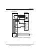
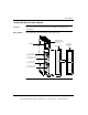
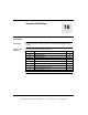
The following figure shows the LED indicators.
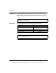
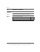
The following table shows the LED descriptions.
Battery
Installation and
Replacement
Considerations
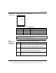
The following procedure describes the installation of a battery.
LED Descriptions
LEDs Color Indication when On
Active Green Bus communication is present.
Bat1 Low Red Battery 1 voltage is low.
Bat2 Low Red Battery 2 voltage is low.
Note: The Bat1 Low and Bat2 Low LEDs turn ON when a battery is not installed,
installed backwards, or in need of replacement.
Active
Bat1 Low
Bat2 Low
Step Action
1 Remove the insulating strip from the plus (+) pole of the battery before inserting
it into the module. This strip is used to insulate the battery when on the shelf.
Note: The battery installed in the module, when shipped, has the insulating strip
in place. Remove this strip and re-install the battery before operation.
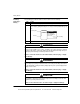
2 When single battery backup is required, install the battery in Battery Slot 1. The
circuitry is designed so Battery 1 supplies the current until it is used up. Battery
2 (when installed) then assumes the load requirement without interruption.
Battery status is indicated via LEDs and Modsoft status bytes.
3 When the controller is in operation, the batteries can be replaced at any time.
Note: When the controller is powered OFF, battery replacement can be done
without RAM loss only when a second functioning battery is installed.
This document provided by Barr-Thorp Electric Co., Inc. 800-473-9123 www.barr-thorp.com