
Hardware reference guide

Simulator Modules
482
35013379 02 October 2007
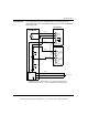
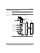
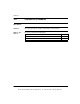
Note: The preceding diagram shows a typical connection between the simulator,
a 140ACI03000 input module, and a 140ACO02000 output module. The simulator
provides a variable 4 ... 20 mA input to the analog in module. The input can then
be read by a Quantum CPU, and, if required, outputted through an analog out
module. For the output module to operate properly, the main current loop must be
active, and, as shown above, 24 Vdc is supplied between terminals 9 and 10 with
a 249 Ohms voltage drop resistor. (For a more detailed description of these
modules, refer to Quantum I/O Modules, p. 489)
This document provided by Barr-Thorp Electric Co., Inc. 800-473-9123 www.barr-thorp.com