
Hardware reference guide

Simulator Modules
35013379 02 October 2007 481
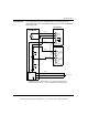
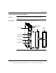
Wiring Diagram The following figure shows the 140XSM01000 generic wiring diagram for the
140Axl03000 input modules, 140Ax002000 output modules, and the 140AMM09000
input/output module.
Red
Black
White
Blue
Yellow
Violet
Black
White
Green/Yellow
Analog Simulator
140XSM01000
Analog Output
Analog Input
140XSM01000 Generic Wiring Diagram for the 140AxI03000 Input Modules,
140AxO02000 Output Modules, and the 140AMM09000 Input/Output Module
V
+
–
–+
L
N
24 Vdc
115...240 Vac
IN 1
IN 2
0-5 Vdc
Monitor
(Typical)
Input X
(Typical)
Input Y
(Typical)
1
2
7
9
10
1
2
3
5
6
7
Wiring Example
249
Ohms
(Load for
illustration purposes)
This document provided by Barr-Thorp Electric Co., Inc. 800-473-9123 www.barr-thorp.com