
Hardware reference guide


Intrinsically Safe Modules
470
35013379 02 October 2007
Agency
Approved Wiring
Diagrams
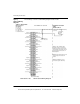
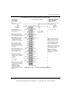
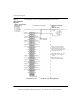
The following is a Cenelec certified wiring diagram for this module.
Output 1 (+) Output 1 (-)
N/C N/C
Output 2 (+) Output 2 (-)
N/C N/C
Output 3 (+) Output 3 (-)
N/C N/C
Output 4 (+) Output 4 (-)
N/C N/C
N/C N/C
N/C N/C
N/C N/C
Output 5 (+) Output 5 (-)
N/C N/C
Output 6 (+) Output 6 (-)
N/C N/C
Output 7 (+) Output 7 (-)
N/C N/C
Output 8 (+) Output 8 (-)
N/C N/C
N/C N/C
I.S. Module
DIO 330 00
Blue Terminal Strip
CHASSIS
GROUND
HAZARDOUS LOCATION
ZONE 1
GROUP IIA, IIB, IIC
(See Notes 1 & 2)
I.S. +8 Vdc
I.S. Field
Device
NON-HAZARDOUS LOCATION
Note 1. Only shielded cables
should be used for connections.
Shields should be left open at the
field end and connected to chassis
ground at the module end.
Note 2. Pins marked “N/C” are not
electronically connected to the
module.
Note 3. All “Output (- )s” are
connected together internally
CENELEC CERTIFICATION
Entity Parameters
per Channel:
Vo = 27.9 Vdc
Io = 121 mA/ch
Po = 840 mW/ch
Co = 84 nf/ch
Lo = 2.2 mH/ch
31001366 Rev 00 140 DIO 330 00 Wiring Diagram
This document provided by Barr-Thorp Electric Co., Inc. 800-473-9123 www.barr-thorp.com