
Hardware reference guide


Intrinsically Safe Modules
464
35013379 02 October 2007
Agency
Approved Wiring
Diagrams
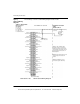
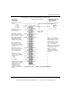
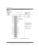
The following is a Cenelec certified wiring diagram for this module.
Input 1 (+) Input 1 (-)
N/C N/C
Input 2 (+) Input 2 (-)
N/C N/C
Input 3 (+) Input 3 (-)
N/C N/C
Input 4 (+) Input 4 (-)
N/C N/C
N/C N/C
N/C N/C
N/C N/C
Input 5 (+) Input 5 (-)
N/C N/C
Input 6 (+) Input 6 (-)
N/C N/C
Input 7 (+) Input 7 (-)
N/C N/C
Input 8 (+) Input 8 (-)
N/C N/C
I.S. Module
DII 330 00
Blue Terminal Strip
Chassis
Ground
HAZARDOUS LOCATION
ZONE 1
GROUP IIA, IIB, IIC
(SEE NOTE 1)
I.S. +8 Vdc
I.S. Field
Device
NON-HAZARDOUS LOCATION
Note 1: Only shielded cables
should be used for connections.
Shields should be left open at the
field end and connected to chassis
ground at the ground screws on
Note 2: Pins marked “N/C” are not
electronically connected to the
module.
Note 3: All “INPUT (- )S” are
connected together internally.
CENELEC CERTIFICATION
Entity Parameters
per Channel:
Vo = 9.6 Vdc
Io = 80 mA/ch
Po = 192 mW/ch
Co = 450 nf/ch
Lo = 694 microH/ch
the backplane.
31001365 Rev 00 140 DII 330 00 Wiring Diagram
This document provided by Barr-Thorp Electric Co., Inc. 800-473-9123 www.barr-thorp.com