
Hardware reference guide


Intrinsically Safe Modules
458
35013379 02 October 2007
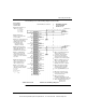
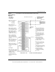
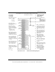
The following is a Cenelec certified wiring diagram for this module.
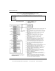
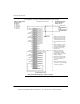
Output 1 (-) Monitor 1 (-)
N/C
Output 1(+)
Output 2 (-) Monitor 2 (-)
N/C
Output 3 (-) Monitor 3 (-)
N/C
Output 4 (-)
Monitor 4 (-)
N/C
N/C N/C
N/C N/C
N/C N/C
Output 5 (-)
Output 5 (+)
N/C
Output 6 (-)
Output 6 (+)
N/C
Output 7 (-)
Output 7 (+)
N/C
Output 8 (-)
Output 8 (+)
N/C
N/C
I.S. Module AIO 330 00
Blue Terminal Strip
Chassis
Ground
HAZARDOUS LOCATION
CLASS 1, DIVISION 1
GROUP A, B, C, D
(SEE NOTE 1)
I.S. Field Device
R-500 OHMS Max
NON-HAZARDOUS LOCATION
Note 1. Only shielded cables
should be used for connections.
Shields should be left open at
the field end and connected to
chassis ground at the module
Note 5. Pins marked “N/C” (Not
Connected) are not electronically
end.
connected to the module.
CENELEC CERTIFICATION
Entity Parameters
per channel:
Output 2 (+)
N/C
Output 3 (+)
Output 4 (+)
Monitor 5 (-)
Monitor 6 (-)
Monitor 7 (-)
Monitor 8 (-)
V
(SEE NOTE 2)
Note 2. More than one device
can be connected as long as
they have differential input and
total input resistance is less
than 500 ohms.
Note 3. The voltmeter is
optional and reads voltage
proportional to the current.
Length of wiring to this terminal
is limited to 1 Meter.
Note 4. Unused channels will
show open loop unless outputs
are shorted as shown for
channel 8.
(See Note 3)
Vo = 29.5 Vdc
Io = 94 mA/Ch
Po = 520 mW/ch
Co = 68 nf/ch
Lo = 4.2 mH/ch
31001364 Rev 00
AIO 330 00 Wiring Diagram (Analog Output)
This document provided by Barr-Thorp Electric Co., Inc. 800-473-9123 www.barr-thorp.com