
Hardware reference guide


Intrinsically Safe Modules
456
35013379 02 October 2007
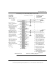
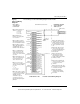
The following is a FM certified wiring diagram for this module.
Output 1 (-)
Monitor 1 (-)
N/C
Output 2 (-)
Output 1 (+)
N/C
Output 3 (-)
Output 2 (+)
N/C
Output 4 (-)
N/C
N/C N/C
N/C N/C
N/C N/C
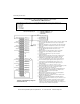
Output 5 (-)
Output 5 (+)
N/C
Output 6 (-)
Output 6 (+)
N/C
Output 7 (-)
Output 7 (+)
Output 8 (+)
N/C
I.S. Module
Terminal Strip
Chassis
Ground
HAZARDOUS LOCATION
CLASS I DIV I GROUP A, B, C, D
CLASS II DIV I GROUP E, F, G
I.S. Field Device
R-500 OHMS Max
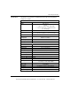
Note 1. Only shielded cables should be used for connections. Shields should
Note 3. Only 140 XBP 0xx 00 backplanes should be used for mounting
this module.
Note 6. The Entity Concept allows interconnection of intrinsically safe
apparatus with associated apparatus not specifically examined in
combination as a system when the approved values of Voc and
Isc for the associated apparatus are less than or equal to Vmax and
CLASS III DIV I
be left open at the field elnd and connected to chassis ground at the
Module end.
Note 2. Pins marked N/C are not electronically connected to the Module.
Imax for the intrinsically safe apparatus and the approved values of
Ca and La for the associated apparatus must be equal to or are
greater than Ci and Li for the intrinsically Safe apparatus plus all
cable parameters.
Ca ≥ Ci + Ccable; La ≥ Li + Lcable; Voc ≤ Vmax; Isc ≤ Imax
Note 7. Simple Apparatus is defined as a device which will neither generate
nor store more than 1.2V, 0.1A, 20uJ, or 25 mW. For examples
switches, Thermocouples, LEDs and RTDs, etc.
Note 8. Wiring methods must be in accordance with National Electrical
Code NFPA 70, Article 504 and ANSI/ISA RP12.6, “Wiring Practices
for Hazardous (classified) Locations Instrumentation
Part I: Intrinsic Safety”.
Note 9. Control room equipment connected to associated apparatus
should not use or generate more than 250Vrms.
Note 10. All modules must be installed in an enclosure that meets the
requirements of ANSI/ISA S82.01
Note 11. No revisions to this drawing without prior FMRC Approval.
Notes Related to FM Certification
Monitor 2 (+)
Monitor 3 (-)
Output 3 (+)
Monitor 4 (-)
Output 4 (+)
Monitor 5 (-)
Monitor 6 (-)
Monitor 7 (-)
Monitor 8 (-)
N/C
Output 8 (-)
N/C
N/C
Note 4. More than one device can be connected in series as long as
they have differential input and total load resistance is less
than 500 ohms.
Note 5. Voltmeter is an optional Voltmeter shown to read voltage
proportional to the current. Wiring to this terminal is limited
to 1 meter.
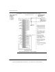
Unused channels will show Open Loop unless shorted as
Shown in Channel 8.
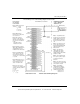
V
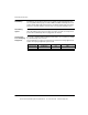
HAZARDOUS LOCATION,
Class I, Div 2 Group A, B, C, D
Note 13. For Division 2 installation, the apparatus shall be installed in
140 AIO 330 00 Wiring Diagram
31001364 Rev 01
requirements of the ultimate application, including access only by the use
of a tool and provision for Division 2 wiring methods.
compliance with the enclosure, mounting, spacing, and segregation
This IS field device should meet Note 7 or should be FM approved with entity concept in Note 6 appropriate for
connection with IS RTD/TC IN Module with concept parameters listed below. The entity parameters listed are per channel.
Voc = 29.5 VDC
Isc = 94 mA/Ch
Ca = 68 nf/Ch
La = 4.2 mH/Ch
Po = 520 mW/Ch
Note 12. For Schneider Electric internal use only. For control sheet, refer
to 19-100986 Rev 1.
This document provided by Barr-Thorp Electric Co., Inc. 800-473-9123 www.barr-thorp.com