
Hardware reference guide


Intrinsically Safe Modules
448
35013379 02 October 2007
Agency
Approved Wiring
Diagrams
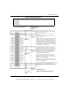
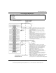
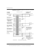
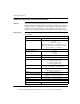
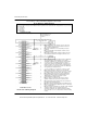
The following is a Cenelec certified wiring diagram for this module.
V1 (-) V1 (+)
N/C Signal 1
N/C
Signal 2
N/C N/C
V3 (-) V3 (+)
N/C
Signal 3
N/C
Signal 4
N/C N/C
V5 (-) V5 (+)
N/C
Signal 5
N/C
Signal 6
N/C N/C
V7 (-) V7 (+)
N/C
Signal 7
N/C
Signal 8
N/C N/C
NON-HAZARDOUS LOCATION
HAZARDOUS LOCATION
ZONE 1
GROUP IIA, IIB, IIC
(SEE NOTE 1)
Note 1. Only shielded twisted pair
cables should be used for connec-
tions. Shields should be left open at
the field end and connected to
chassis ground at the ground
screws on the backplane.
Note 2. A dropping resistor 100
Ohms is across the signal and V(-)
Note 3. Three wire transmitters
should be provided power only
from the module. An external
I.S. Module AII 330 10
Blue Terminal Strip
CENELEC CERTIFICATION
Entity Parameters
per Channel:
Vo = 23.8 Vdc
Io = 112 mA/ch
Po = 622 mW/ch
Co = 127 nf/ch
Lo = 2.9 mH/ch
V2 (-) V2 (+)
V4 (-) V4 (+)
V6 (-) V6 (+)
V8 (-) V8 (+)
(SEE NOTE 1)
I.S. 3 WIRE
TRANSMITTER
I.S. 2 WIRE
TRANSMITTER
pins of each channel. V(-) is
internally connected to I.S. ground.
power supply should not be used.
Note 4. Pins marked “N/C” (Not
Connected) are not electronically
connected to the module.
I.S. + 14.5 Vdc
31001363 Rev 00 140 AII 330 10 Wiring Diagram
This document provided by Barr-Thorp Electric Co., Inc. 800-473-9123 www.barr-thorp.com