
Hardware reference guide

Intrinsically Safe Modules
436
35013379 02 October 2007
Agency
Approved Wiring
Diagrams
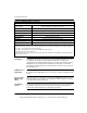
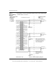
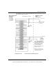
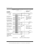
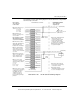
The following is a Cenelec certified wiring diagram for this module configured with
an RTD/Resistance connection.
I Source 1 (+) I Source 1 (-)
V Sense 1 (+)
V Sense 1 (-)
I Source 2 (+) I Source 2 (-)
N/CN/C
V Sense 2 (+) V Sense 2 (-)
I Source 3 (+) I Source 3 (-)
V Sense 3 (+) V Sense 3 (-)
N/CN/C
I Source 4 (+) I Source 4 (-)
V Sense 4 (+) V Sense 4 (-)
I Source 5 (+) I Source 5 (-)
V Sense 5 (+) V Sense 5 (-)
N/CN/C
I Source 6 (+) I Source 6 (-)
V Sense 6 (+) V Sense 6 (-)
I Source 7 (+) I Source 7 (-)
V Sense 7 (+) V Sense 7 (-)
N/CN/C
I Source 8 (+) I Source 8 (-)
V Sense 8 (+)
V Sense 8 (-)
I.S. Module AII 330 00
Blue Terminal Strip
Chassis
Ground
Chassis
Ground
Chassis
Ground
HAZARDOUS LOCATION
ZONE 1
Group IIA, IIB, IIC
(SEE NOTE 1)
4 Wire RTD/Resistor
Connection
(SEE NOTE 1)
2 Wire RTD/Resistor
Connection
(SEE NOTE 1)
3 Wire RTD/Resistor
Connection
Note 1. Only shielded twisted pair
cables should be used for connec-
tions. Shields should be left open at
the field end and connected to
chassis ground at the ground
screws on the backplane.
Note 2. Pins marked “N/C”
(Not Connected) are not
electronically connected to
the module.
NON-HAZARDOUS LOCATION
CENELEC CERTIFICATION
Entity Parameters
per Channel:
V
o
= 15.5 Vdc
I
o
= 276 mA/ch
P
o
= 1.07 W/ch
C
o
= 0.508 μF/ch
L
o
= 466 μH/ch
31001362 Rev 00 140 AII 330 00 RTD Wiring Diagram
This document provided by Barr-Thorp Electric Co., Inc. 800-473-9123 www.barr-thorp.com