
Hardware reference guide

Intrinsically Safe Modules
35013379 02 October 2007 433
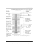
Thermocouple/
Millivolt Module
Specifications
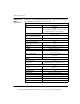
The following table shows the specifications for the Thermocouple/Millivolt module.
Thermocouple/Millivolt Module Specifications
Number of Channels 8
LEDs Active (Green)
F (Red)
1 ... 8 (Red). Indicated channel is out of range - Broken wire condition is detected.
TC Types and Ranges
Types J K E T S R B Ranges (°C) -210 ... +760
-270 ... +1370
-270 ... +1000
-270 ... +400
-50 ... +1665
-50 ... +1665
+130 ... +1820
Millivolt Ranges -100 mV ... +100 mV*
-25 mV ... +25 mV*
*Open circuit detect can be disabled on these ranges
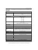
TC Circuit Resistance/Max
Source Resistance
200Ω max for rated accuracy
Input Impedance >1MΩ
Input Filter Single low pass @ nominal 20 Hz. Plus notch filter at 50/60 Hz
Normal Noise Rejection 120 dB min @ 50 or 60 Hz
Cold Junction Compensation
(CJC)
Internal CJC operates 0 ... 60° C (errors are included in the accuracy
specification). The connector door must be closed. Remote CJC can be
implemented by connecting the TC (which monitors the external junction block
temperature) to channel 1. Types J, K, and T are recommended for best accuracy.
Programming Software Modsoft Ver. 2.61or higher
Resolution
TC Ranges Choice of: 1° C (Default) 0.1° C 1° F 0.1° F
Millivolt Ranges +/- 100 mV range, 3.05 μV (16 bits)
+/- 25 mV range, 0.76 μV (16 bits)
TC Absolute Accuracy (see Note 1)
Types J, K, E, T (see Note 2) +/- 2° C +/- 0.1% of reading
Types S, R, B (see Note 3) +/- 4° C +/- 0.1% of reading
Millivolt Absolute Accuracy
@ 25°C +/- 20 μV +/- 0.1% of reading
Accuracy Drift w/ Temperature 0.15 μV/°C + 0.0015% of reading/°C max.
This document provided by Barr-Thorp Electric Co., Inc. 800-473-9123 www.barr-thorp.com