
Hardware reference guide

Intrinsically Safe Modules
428
35013379 02 October 2007
I/O Map Register
Assignments
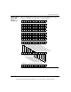
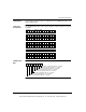
The 140AII33010 module requires nine contiguous input (3x) registers assigned as
follows.
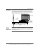
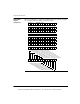
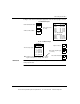
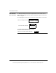
I/O Map Status
Byte (Inputs)
The most significant bit in the I/O map status byte is used for this module.
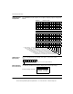
Modsoft Module
Zoom Selections
Use Modsoft’s Module Zoom feature to display and select the input range.
Register 1 Channel 1 data
Register 2 Channel 2 data
Register 3 Channel 3 data
Register 4 Channel 4 data
Register 5 Channel 5 data
Register 6 Channel 6 data
Register 8 Channel 8 data
Register 7 Channel 7 data
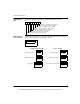
Register 9 Input Status Word
1 2 3 4 5 6 7 8 9 10 11 12 13 14 15 16
1 = Broken Wire (4 ... 20 mA only) or out of range on Channel 8
1 = Broken Wire (4 ... 20 mA only) or out of range on Channel 7
1 = Broken Wire (4 ... 20 mA only) or out of range on Channel 6
1 = Broken Wire (4 ... 20 mA only) or out of range on Channel 5
1 = Broken Wire (4 ... 20 mA only) or out of range on Channel 4
1 = Broken Wire (4 ... 20 mA only) or out of range on Channel 3
1 = Broken Wire (4 ... 20 mA only) or out of range on Channel 2
1 = Broken Wire (4 ... 20 mA only) or out of range on Channel 1
87654321
MSB
1= Broken wire (4 ... 20 mA only) on one or more input channels
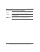
4 to 20mA 0 - 16,000
4 to 20mA 0 - 4095
0 to 20mA 0 - 20,000
0 to 25mA 0 - 25,000
Channel x Range Selection
This document provided by Barr-Thorp Electric Co., Inc. 800-473-9123 www.barr-thorp.com