
Hardware reference guide

Intrinsically Safe Modules
35013379 02 October 2007 427
Configure each channel (1 through 8) appropriate to the module input type selected.
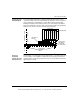
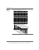
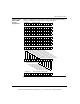
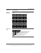
140AII33010 The following information pertains to configuration of the 140AII33010 intrinsic safe
analog input module.
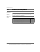
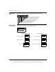
For RTD Module Input:
Enable
Disable
4 Wire
3 Wire
2 Wire
Channel Enable/Disable:
4-Wire /3-Wire /2-Wire:
Pt100, -200 to 850
Pt200, -200 to 850
Pt500, -200 to 850
Pt1000, -200 to 850
Ni 100, -60 to 180
Ni 200, -60 to 180
Ni 500, -60 to 180
Ni1000, -60 to 180
R, 0 to 766.66 OHM
R, 0 to 4000 OHM
APt100, -100 to 450
APt200, -100 to 450
APt500, -100 to 450
APt1000, -100 t0 450
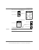
RTD Type (Pt, Ni,
R, A Pt)
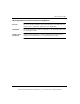
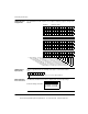
For TC / mV Module Input:
No
Yes
25
100
Undefined
J, gain=25
K, gain=25
E, gain=25
T, gain=100
S, gain=100
R, gain=100
B, gain=100
Thermocouple Type:
Open circuit test:
Raw output, amplifier gain:
Yes
No
This channel installed:
(see Note)
Note: A gain of 25 produces readings with + 100mV.
A gain of 100 produces readings with + 25mV.
This document provided by Barr-Thorp Electric Co., Inc. 800-473-9123 www.barr-thorp.com