
Hardware reference guide

Intelligent/Special Purpose
35013379 02 October 2007 415
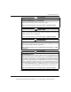
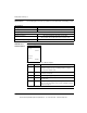
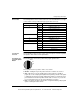
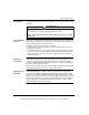
Error Codes The following table shows the number of times the Com Act LED blinks for each type
of error and the codes possible for that group (all codes are in hex).
Front Panel
Controls
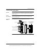
The Hot Standby module has three controls on the front panel: a function keyswitch,
a designation slide switch, and an update button.
Keyswitch and
Program Update
Button
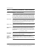
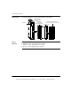
The following figure shows the keyswitch and program update button.
The keyswitch has three positions: off line, xfer, and run:
z Off line – Putting the key in this position takes the controller out of service.
z Xfer – When the key on the standby unit is in this position, the standby is
prepared to receive a full program update from the primary controller. The update
is initiated by pressing the program update button, which is located on the front
panel between the function keyswitch and the cable connectors. If you turn the
key on the primary unit to xfer, the system will ignore your action.
z Run – The switch should be in this position except when initiating a full program
update or taking the module off line.
Number of Blinks Code Error
1 6900 error in additional transfer calculation
2 6801 ICB frame pattern error
6802 head control block error
6803 bad diagnostic request
6804 greater than 128 MSL user loadables
4 6604 powerdown interrupt error
6605 UART initialization error
5 6503 RAM address test error
6 6402 RAM data test error
7 6301 PROM checksum error
8 C101 no hook timeout
C102 read state RAM timeout
C103 write state RAM timeout
C200 powerup error
Off line
Xfer
Run
This document provided by Barr-Thorp Electric Co., Inc. 800-473-9123 www.barr-thorp.com