
Hardware reference guide

Intelligent/Special Purpose
406
35013379 02 October 2007
Server
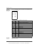
Connector
Signals
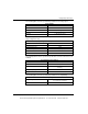
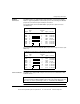
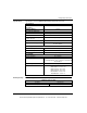
The following figure shows the server connector signals (from left to right) 50 - 34.
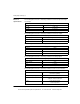
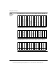
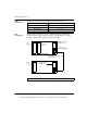
The following figure shows the server connector signals (from left to right) 33 - 18.
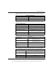
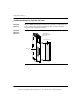
The following figure shows the server connector signals (from left to right) 17 - 1.
50 49 48 47 46 45 44 43 42 41 40 39 38 37 36 35 34
N/C
N/C /Reference Output Low
N/C /Reference Output High
N/C /Sine Input Low
N/C /Sine Input High
N/C /Cosine Input Low
N/C /Cosine Input High
Overtemp Low
Overtemp High
Drive Enable Common
Drive Enable Contact (NC)
Drive Enable Contact (NO)
Drive Fault
Velocity - / Phase Common
N/C / Phase C
N/C / Phase B
Velocity + / Phase A
33 32 31 30 29 28 27 26 25 24 23 22 21 20 19 18
Analog Input
Analog Common
Analog Output
High Speed Input
Auxiliary Input 7
Auxiliary Input 6
Auxiliary Input 5
Auxiliary Input 4
Home
(Auxiliary Input 3)
Limit CCW
(Auxiliary Input 2)
Limit CW
(Auxiliary Input 1)
Auxiliary Output 3
Auxiliary Output 2
Brake Output
(Auxiliary Output 1)
24 V Common
24 Vdc
17 16 15 14 13 12 11 10 9 8 7 6 5 4 3 2 1
N/C (Not Connected)
N/C
N/C
N/C
N/C
Encoder 2 Mark-
Encoder 2 Mark+
Encoder 2 Phase B-
Encoder 2 Phase A-
Encoder 2 Phase B+
Encoder 2 Phase A+
Encoder 1 Mark-
Encoder 1 Mark+
Encoder 1 Phase B-
Encoder 1 Phase B+
Encoder 1 Phase A-
Encoder 1 Phase A-
This document provided by Barr-Thorp Electric Co., Inc. 800-473-9123 www.barr-thorp.com