
Hardware reference guide

Intelligent/Special Purpose
35013379 02 October 2007 405
Modbus
Connectors
The MSX modules are equipped with a 9-pin, RS-232C connector that supports
Modicon’s proprietary Modbus communication protocol. The following is the Modbus
port pinout connections for 9-pin and 25-pin connections.
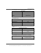
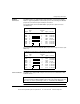
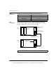
The following figure shows the MSX Modbus port pinouts to 9-pin connectors
(AS-W956-xxx).
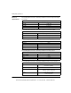
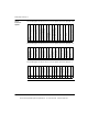
The following figure shows the MSX Modbus port pinouts for 25-pin connectors (AS-
W955-xxx).
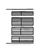
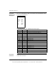
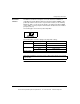
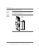
Servo Connector The MSX is also equipped with a 50-pin servo connector for communication with
feedback devices.
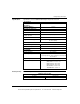
Msx Modbus Port Pinouts to 9-Pin Connectors (AS-W956-xxx)
Signal
MSx
Pin
Computer
Pin
Signal Function
TXD
RXD
GND
DTR
DSR
RTS
CTS
1
2
3
4
5
6
7
8
1
3
2
5
6
4
7
8
RXD
TXD
GND
DSR
DTR
RTS
CTS
No Connection
Shield
Serial data
Serial data
Ground
Control line
Control line
Control line
Control line
MsxModbus Port Pinouts for 25-Pin Connectors (AS-W955-xxx)
Signal
MSx
Pin
Computer
Pin
Signal Function
TXD
RXD
GND
DTR
DSR
RTS
CTS
1
2
3
4
5
6
7
8
1
2
3
7
6
20
4
5
RXD
TXD
GND
DSR
DTR
RTS
CTS
No Connection
Shield
Serial data
Serial data
Ground
Control line
Control line
Control line
Control line
Note: The tables below show the 50-pin servo connector signals. Pin numbers
correspond to both the MSB and MSC modules. When the signals differ from each
other, they are shown separated by a slash (i.e., Pin Number 34, MSB/MSC).
This document provided by Barr-Thorp Electric Co., Inc. 800-473-9123 www.barr-thorp.com