
Hardware reference guide

Intelligent/Special Purpose
404
35013379 02 October 2007
Front Panel
Indicators and
Descriptions
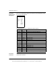
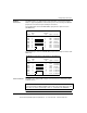
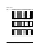
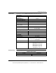
There are 17 LED indicators visible on the front panel. The following figure shows
the front panel LED indicators.
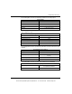
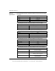
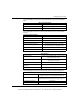
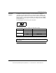
The following table shows the 140MSX10100 LED descriptions.
Front Panel
Connectors
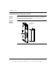
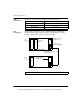
There are two connectors located on the front of the module: the Modbus Connector
and the Servo Connector.
LEDs Color Indication when On
Active Green Bus communication is present.
Ready Green The module has passed powerup diagnostics.
+ Lim ok Green Digital Input 1 active.
- Lim ok Green Digital Input 2 active.
Home Green Digital Input 3 active.
In 4 Green Digital Input 4 active.
In 5 Green Digital Input 5 active.
In 6 Green Digital Input 6 active.
In 7 Green Digital Input 7 active.
Drv Flt Red Fault signal from drive.
Drv En Green Drive enabled.
Out 1 Green Digital Output 1 active.
Out 2 Green Digital Output 2 active.
Out 3 Green Digital Output 3 active.
Modbus Green Communications are active on the Modbus port.
Moving Amber Motor is moving.
In Pos Amber Motion is within the in position of the final target.
Active
Ready
+ Lim ok
- Lim ok
Home
In 4
In 5
In 6
In 7
Drv Flt
Drv En
Out 1
Out 2
Out 3
Modbus
Moving
In Pos
This document provided by Barr-Thorp Electric Co., Inc. 800-473-9123 www.barr-thorp.com