
Hardware reference guide

Intelligent/Special Purpose
35013379 02 October 2007 403
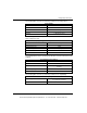
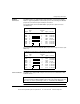
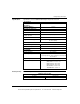
The following table shows the electrical specifications for the motor temperature
input.
The following table shows the electrical specifications for the encoder feedback
interface.
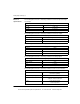
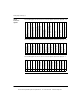
The following table shows the electrical specifications for the drive interface.
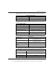
The following table shows the electrical specifications for power requirements.
Motor Temperature Input
Normal State Short circuit, 2 mA sink max
Fault State Open circuit
Isolation 500 Vac to system bus
Encoder Feedback Interface
Input Range -0.7 ... 7 Vdc
Input Impedance 145 Ω, nominal
Differential Signals, High +2 V differential, min
Differential Signals, Low -2 V differential, min
Maximum Encoder Frequency 200 kHz square wave (55% ... 45% with
less than 15 degrees of quadrature error)
Isolation 500 Vac to system bus with external power supply
Minimum Encoder Pulse Width 1 ms
Drive Interface
Drive Fault Input True high, TTL compatible relative to remote common,
10 K internal pull-up resistor
Drive Enable Relay Form C contacts. 120 Vac @ 0.1 A resistive.
30 Vdc @ 0.5 A resistive
Current Command Voltages +/- 10 Vdc
Current Command Summing
Accuracy
0 +/- 0.1 Vdc
Current Commands 3 mA drive capability
Power Requirements
Main Power Input 5 V +/- 5% @ 750 mA
(with no encoders or resolvers attached, output off)
Main Power Input 5 V +/- 5% @ 1000 mA
(with maximum encoder and resolver load, outputs on)
Hot Swap Surge Current Less than 5 A
Bus Current Required MSB Module: 700 mA. MSC Module: 1000 mA
This document provided by Barr-Thorp Electric Co., Inc. 800-473-9123 www.barr-thorp.com