
Hardware reference guide

Intelligent/Special Purpose
35013379 02 October 2007 389
LED Indicators
and Descriptions
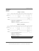
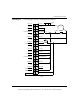
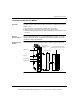
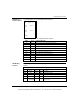
The following figure shows the ESI06210 LED indicators.
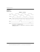
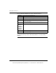
The following table shows the ESI06210 LED descriptions.
LED Blinking
Sequence
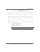
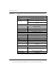
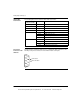
The following table shows the blinking sequence of the F, Status, Error 1, and Error
2 LEDs.
LEDs Color Indication when On
R Green The module has passed powerup diagnostics
Active Green Bus communication is present
F Red The module has detected a fault
Rx1 Green Received data on RS-232C Port 1
Tx1 Green Transmitted data on RS-232C Port 1
Rx2 Green Received data on RS-232C Port 2
Tx2 Green Transmitted data on RS-232C Port 2
Status Yellow Status
Error 1 Red There is an error condition on Port 1
Error 2 Red There is an error condition on Port 2
ActiveR
Error 1
F
Error 2
Rx1
Tx1
Rx2
Tx2
Status
LEDs and Blinking Sequence
F Status Error 1 Error 2 Description
F Status Error 1 Error 2 Description
OFF ON OFF OFF Programming mode
OFF OFF ON N/A Serial Port 1 incurred a buffer overrun
OFF OFF N/A ON Serial Port 2 incurred a buffer overrun
N/A Blinking (See
the next table)
OFF OFF The ASCII module is in kernal mode and may
have an error
This document provided by Barr-Thorp Electric Co., Inc. 800-473-9123 www.barr-thorp.com