
Hardware reference guide

Intelligent/Special Purpose
386
35013379 02 October 2007
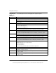
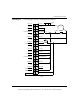
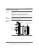
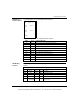
The preceding wiring diagram shows single ended connections for:
Refer to I/O Configuration for 140EHC20200, p. 342 for both differential pulse
encoder input and single ended or differential quadrature encoder input wiring
diagrams.
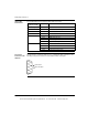
Terminal 1 Pulse encoder input (sinking device)
Terminal 3 Input 1B count UP direction
Terminal 5 Unused hardwire Preset tied high
Terminal 7 Output Reset tied high, not required; outputs not used
Terminal 11 Hardware enabled (software enable also required using predefined
Modzoom or 4X register
Terminal 17 Required Vref+ connection
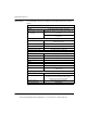
Terminal 21
Terminal 23
Terminal 25
Terminal 27
Terminal 31
Terminal 37
Counter 2 not used. These terminals must be connected VREF+.
Terminal 39 Required Output Supply Return
Terminal 40 Required Output Supply
This document provided by Barr-Thorp Electric Co., Inc. 800-473-9123 www.barr-thorp.com