
Hardware reference guide

Intelligent/Special Purpose
384
35013379 02 October 2007
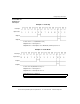
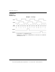
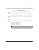
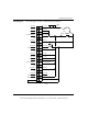
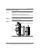
Wiring Diagram
Signal
Descriptions
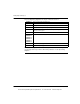
The following table shows the wiring diagram for signal descriptions.
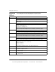
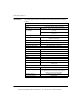
Parameter Description/Usage
INPUT A Single ended or differential count input or Phase A for quadrature mode.
Single ended (active low only) uses Input 1A+ and/or Input 2A+.
Input 1A- and/or Input 2A- are not connected. Differential input encoders use both plus (+) and
minus (-) inputs.
INPUT B Direction level for non-quadrature devices or Phase B for quadrature mode.
Direction inputs for non-quadrature input devices are:
Count Up = High Voltage Level
Count Down = Low Voltage Level
For single ended Input devices, only Input 1B+ and/or Input 2B+ are used. Input 1B- and 2B-
are not connected. Differential input encoders use both plus (+) and minus (-) inputs.
PRESET C Presets count register(s). Low level causes preset.
For single ended Preset inputs, only Preset 1C+ and/or Preset 2B+ are used. Preset 1C- and
2C- are not connected. Differential input encoders use both plus (+) and minus (-) inputs.
OUTPUT RESET 0 Low level resets Outputs 1A, 1B, 2A, and 2B to OFF if latched.
For single ended Reset inputs, only Reset 10+ and/or Reset 20+ are used. Reset 10- and 20-
are not connected. Differential input encoders use both plus (+) and minus (-) inputs.
ENABLE Low level enables counting.
For single ended Enable inputs, only Enable 1+ and/or Enable 2+ are used. Enable 1- and 2-
are not connected. Differential input encoders use both plus (+) and minus (-) inputs.
VREF Field input device power source connection. Also, connect any unused (+) inputs to the group
VREF terminal or the one in use (30 Vdc max).
Group A = Terminal 17
Group B = Terminal 37
Group A and Group B VREF supplies can be different voltage levels.
LO FILTER SEL Enables the internal 200 Hz filter when connected to Return Terminal 39.
OUTPUT Internal FET switches connect the output supply wired to Terminal 40 to the Output 1A, 1B, 2A,
2B terminals at output assert times.
POWER SUPPLY External 24 Vdc power supply (+) connection. Required for the module interface and for Outputs
1A, 1B, 2A, and 2B.
RETURN External 24 Vdc power supply (-) connection. Required for the module interface and for Outputs
1A, 1B, 2A, and 2B.
This document provided by Barr-Thorp Electric Co., Inc. 800-473-9123 www.barr-thorp.com