
Hardware reference guide


Intelligent/Special Purpose
378
35013379 02 October 2007
Timing Diagrams
and Parameters
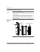
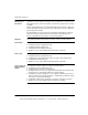
This section includes timing diagrams and parameters for the 140EHC20200
counter modules. Timing diagrams and a timing parameter table for the
140EHC20200 counter module are shown below.
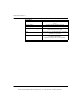
The following table shows the EHC20200 timing parameters.
Timing Parameters Limits
Filter
200 Hz
No Filter
500 khz
Tdly1 Count to Output Assertion Delay (MAX) 4.8 ms 40 μs
Tdly2 Preset/Reset to Output Delay (MAX) 4.8 ms 40 μs
Tpw1 Count/Reset Pulse Width (MIN) 2.5 ms 1 μs
Tpw2 Preset Pulse Width (MIN) 2.5 ms 500 μs
Tst Enable/Reset/Preset to Count Setup Time (MIN) 2.5 ms 2 μs
Thold Enable/Reset to Count Hold Time (MIN) 2.5 ms 2 μs
Note: The timing parameter limits are measures at the module field terminal
connector at the logic low threshold level.
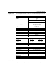
Tpw 1
Thold
Tst
Tst
Tst
Tdly1
Tdly2
Tpw 2
Tpw 1
Count Input
Enable
Preset
Reset
Output Assertion
EHC20200 Timing Diagrams
This document provided by Barr-Thorp Electric Co., Inc. 800-473-9123 www.barr-thorp.com