
Hardware reference guide


Intelligent/Special Purpose
376
35013379 02 October 2007
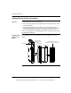
LED Indicators
and Descriptions
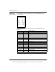
The following figure shows the LED indicators for the EHC20200 High Speed
Counter module.
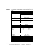
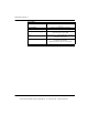
The following table shows the LED descriptions for the EHC20200 high speed
counter.
LED Descriptions
LEDs Color Indication when On
Active Green Bus communication is present
F Red Indicates internal fuse blown or loss of output power
supply
In 1 Green Counter 1 input
En 1 Green Enable Counter 1 input
Pre C1 Green Preset Counter 1 input
Res 01 Green Reset Output 1A, 1B
In 2 Green Counter 2 input
En 2 Green Enable Counter 2 input
Pre C2 Green Preset Counter 2 input
Res 02 Green Reset Output 2A, 2B
Out 1A Green Counter 1A output
Out 1B Green Counter 1B output
Out 2A Green Counter 2A output
Out 2B Green Counter 2B output
Active
F
In 1
En 1
Pre C1
Res 01
Out 1A
Out 1B
In 2
En 2
Pre C2
Res 02
Out 2A
Out 2B
This document provided by Barr-Thorp Electric Co., Inc. 800-473-9123 www.barr-thorp.com