
Hardware reference guide


Intelligent/Special Purpose
35013379 02 October 2007 371
*Refer to Load Values Command section for the maximum values that may be used
by the module.
The next lines apply ONLY IF the counter is in 1x32, Output Assert Mode:
*Refer to Load Values Command section for the maximum values that may be used
by the module.
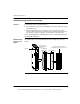
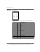
The following figure shows the number of counters in output assertion.
The next lines apply ONLY IF the counter is in 2x32, No Output Assert Mode:
*Refer to Load Values Command section for the maximum values that may be used
by the module.
The next line applies ONLY IF the counter is in Rate Sample Mode:
Counter 2 Maximum Count: * 0 DEC
Counter 2 Setpoint (alarm): * 0 DEC
Time Output On: 0 DEC milliseconds (16383 maximum)
Words 2-3: Counter 1 Maximum Count: * 0 DEC
Words 4-5: Counter 2 Maximum Count: * 0 DEC
Rate Sample Timer X: 0 DEC milliseconds (65535 maximum)
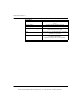
Note: Any Number of counters, output assertion selection pop-up menu can be
used as they reflect each other.
2x16 Assert Outp
2x32 Assert Outp
2x32 No Assert
Rate Sample Mode
Number of counters, output assertion:
This document provided by Barr-Thorp Electric Co., Inc. 800-473-9123 www.barr-thorp.com