
Hardware reference guide

Intelligent/Special Purpose
35013379 02 October 2007 357
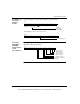
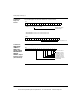
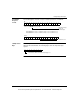
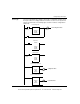
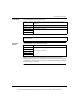
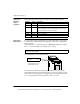
User Logic The User Logic illustrated accomplishes the module’s configuration and then causes
the input counter to be displayed after the first three successive scans by the PLC
when it is in RUN mode. The following figure shows the module’s configuration in
RUN mode.
300001
#00256
TEST
#00001
300001
#00512
TEST
#00001
000011
000010
000010
000012
Read Counter
Load Configuration
Load Configuration Done
Load Values
Check Configuration Echo
Check Load Values Echo
Configuration Done
Load Values Done
000011
000012
000010
400101
400001
BLKM
#00006
400201
400001
BLKM
#00006
400301
400001
BLKM
#00006
P
P
This document provided by Barr-Thorp Electric Co., Inc. 800-473-9123 www.barr-thorp.com