
Hardware reference guide

Intelligent/Special Purpose
356
35013379 02 October 2007
Read Input
Counter
Command
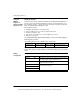
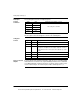
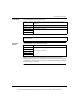
The following table shows the read input registers.
When this command is issued, the content of the input pulse counter is retrieved.
The 3X register content would appear as shown in the following table.
3x Register
Content
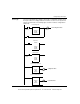
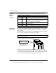
Reset of Latched
Outputs
If register 400103 in the Module Configuration Table has been set to 4200, Output
1A would have been latched on at setpoint and Output 1B latched on at maximum
count. Wiring Diagrams 2 and 4 show how the encoder Z outputs could be used to
reset the latched outputs. The minimum pulse width to reset outputs is 1 μs.
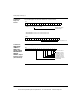
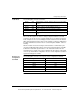
40301 0300 READ INPUT COUNTER command
40302 0000
Not used by this command
40303 0000
40304 0000
40305 0000
40306 0000
Register Value Description
300001 0300 Command echo
300002 XXXX Current input count
300003 0000 Zeros as the count will not exceed 100. For counts above 65,536,
this register is a multiplier. As an example: 30002 has a value of
324 and 30003 a value of 3.The total count is (65,536 x 3) + 324 =
196,932
300004 0000 Counter 2 is disabled
300005 0000 Counter 2 is disabled
300006 0X00 X is the field power indicator
This document provided by Barr-Thorp Electric Co., Inc. 800-473-9123 www.barr-thorp.com