
Hardware reference guide

Intelligent/Special Purpose
354
35013379 02 October 2007
Using I/O
Mapped
Registers to
Operate the High
Speed Counter
COUNT UP Example
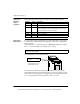
Field connections for this example are illustrated in the EHC202 wiring diagrams 1–
4 in this section. The maximum allowable Vref value is 30 Vdc. Input pulse on-off
threshold levels for the 5 ... 24 Vdc Vref range are listed in the module specification
table. The minimum differential input is 1.8 V.
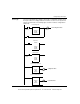
The following user logic:
z Configures the module to count up from zero.
z Turns an output on for one count at a setpoint value of 50.
z Continues counting to 100.
z Rolls over to zero and turn on a second output for one count.
z Repeats the operation.
See 140EHC20200 High Speed Counter Module, p. 372 for counter timing diagrams
illustrating output on times.
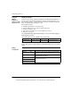
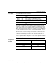
The following table shows the I/O Map register assignments.
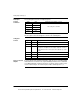
In this example, block moves are used to load the operating parameters into the
module. This requires pre-defined tables be established. Register values are in HEX
format.
Module
Configuration
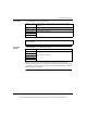
The following table shows the module configurations.
Module Input Ref Output Ref Description
140EHC20200 300001-300006 400001-400006 EHC20200 High Speed
400101 0140 CONFIGURE command, Disable Counter 2
400102 0000 Pulse input, two 16 bit counters, output assert on Rate Sample
OFF, disable outputs at bus communication loss
400103 3100 Output 1A on at setpoint, Output 1B on at maximum count +1
Output 2A and 2B are disabled
400104 0000
Not used by this command
400105 0000
400106 0000
This document provided by Barr-Thorp Electric Co., Inc. 800-473-9123 www.barr-thorp.com